
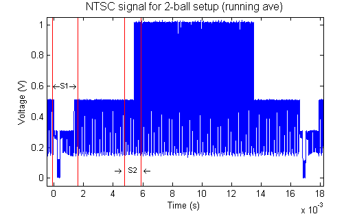
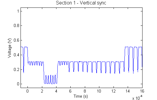
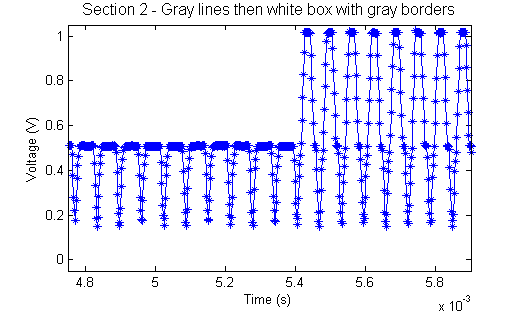
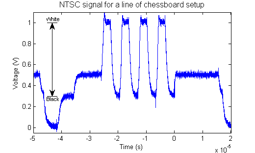
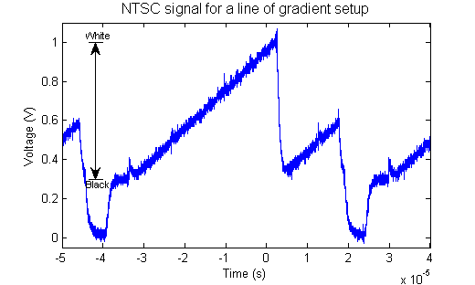
The original goal of this project was to implement a 'soft' processor on FPGA and then create an NTSC video output peripheral for it to control to do something interesting. The advantage of this configuration is the ability to program the FPGA in a similar way to a microcontroller, while having a complete system on chip, with the processor and all its peripherals implemented on the same hunk of silicon on the FPGA board. However, our team encountered too much sadness from the Xilinx MicroBlaze soft processor software and had to settle for implementing only the peripheral portion. NTSC is a television interfacing standard named for the National Television System Committee. It is a very old standard, having been updated several times over its 70 year history to include technical advances such as color. This one wire analog signal varies between 0 and 1V according to various timings and synchronizations in order to display each line on the tv with a grayscale image, whose values vary from 0.3V(black) to 1V(white) (voltages less than 0.3V, often called 'blacker than black', show up as normal black on most TVs). The signal consists of horizontal syncs, horizontal line data, and a vertical sync. The horizontal sync happens once per line and is a 4.7us long period where the wire is at 0V. Next comes a 5.9 us prescan region called the 'back porch' followed by 51.5us of visible data, with the grayscale set by the the output voltage being somewhere between 0.3V and 1V. A vertical sync happens after each set of horizontal lines have been sent and tells the TV to move the elctron beam back to the top of the TV to get ready for the next frame. Because NTSC is interlaced, there is a vertical sync after the odd lines, and another after the even lines. The vertical synchronization sequence itself is the same in both cases, the difference is whether it occurs in between two lines, or in the middle of a single line (a half line on either side of it). In the first case, even lines of the image follow. In the second case, odd lines follow.
EE281 lab4, timing on Page 2
The way we actually implemented this on FPGA was via verilog state machines to control the timing and an 8wire parallel bus to an 8bit D/A converter to output the proper analog voltage signals to the television video imput. The verilog files are available below. Presently, the bouncing ball implementation is hardcoded directly into the NTSC module.
top level module
NTSC module
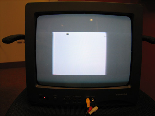
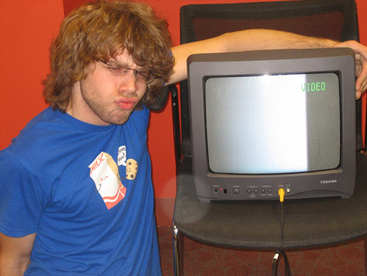
By the end of the project, we managed to create several NTSC demos. We had wanted to make a game, so the first thing we made was chess. We made a black and white test pattern with the same number of squares as a chessboard, flipped the TV over, and then played chess on it. We also implemented a bouncy square ball that bounces around inside a box on screen to show that we had dynamic control of the video signal.

Boris and Dan's Expo poster, a new powerpoint file
Other FPGA bitfiles: (right-click save as)