Multiplexor
The multiplexor takes in numerous inputs and a selector, and then output the value of the input selected by the selector. This type of behavior is useful because it allows a single component to perform multiple functions based on the selected input. The multiplexor used in our CPU is a 32 by 32 multiplexor, as shown below.

A critical component of the above-shown 32:1 multiplexor is the cyan-colored 32-bit decoder, pictured towards the upper-left of the multiplexor diagram. This decoder is broken-down here:

Since the 32 bit mux consists of 1 bit multiplexors, we tested the one bit mux first before making the 32 by 32 mux. The result of the one bit mux is shown below, and the signals are: Start, select, input A, input B, output, and done.
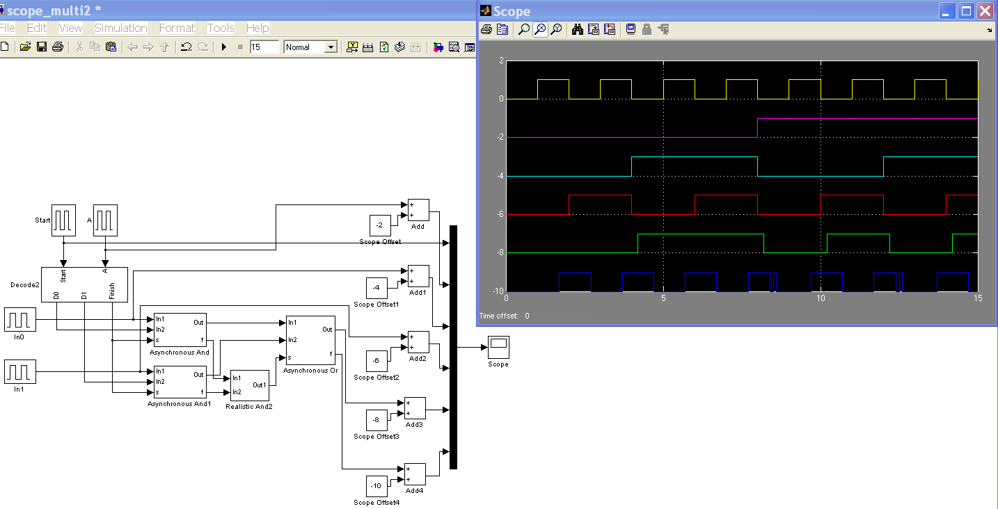
As you can see, start and done signals, the first and last signals, corresponds with each other with a slight lag due to gate processing. The pink signal is the selector, which means that the output should reflect the first input when selector is 0, and reflect the second input when selector is 1. The results are as expected, so we built and tested a 4 input mux, the result of which is more complicated and not shown here. Based on those, we built the 32 by 32 mux.
D-latch
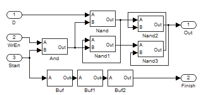
D-latch, or gated data latch, is a major component of the register file for the CPU. It holds and output the same value until told otherwise. When write enable, WrEn, is off, then the input D is ignored and the D-latch outputs the previous, or the original value it have, when start is on. When the write enable is on, then D-latch replace the original value with input D and then output it. In our implementation, the D-latch consists of two pairs of nand gates, with the write enable and start signals collectively acting as the enable.
32 bit register
Creating a 32 by 32-bit asynchronous register was similar to making a 32 by 32-bit clocked register, with the critical difference being that rather than having a clock, there is a start signal that propagates through each stage of the process, with each section producing a finish signal that acts as the start signal of the following section. Below the main diagram of our register file:
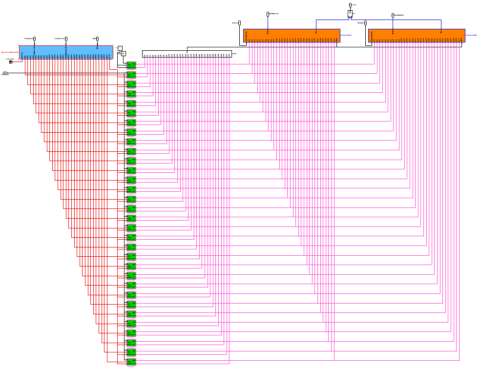
The blue block is a specialized 32-bit decoder, the two orange blocks are two 32-to-1 multiplexors, and the 32 green blocks are gated D-latches. The white blocks are basic asynchronous gates.
The register file uses Simulink’s built-in ability to perform gate operations on multi-bit inputs. The decision to utilize this functionality (as opposed to doing everything for each individual bit) was made after we realized that there would be over 2,000 wires that would need to be connected manually in the main diagram if we decided to have one wire for each of the 32 bits in each of the 32 registers for both the Read A and the Read B outputs.
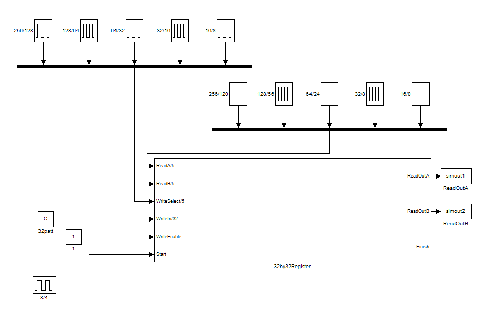
We created various test benches to make sure that each of our systems worked. As an example, one phase of the test bench for the 32 by 32 register is included above. In this particular test bench, we attempt to write a particular pattern to each of the 32 registers in order. Read A gives the output from each register right before writing to it, and Read B gives the output from the register during the same phase that the register is written to. Sure enough, Read A is composed of random data for each register file while Read B outputs the pattern that we expect. This is just an example of one way that we tested our components.
One especially interesting thing we noted was that it took only 25 delays from the time that the register received the start signal to the time that the register outputted the finish flag, despite having thousands of wires in-between. (One delay is equal to the time that it takes to resolve a basic gate; even one of our basic asynchronous gates needs several delays to resolve). This is a great example of what parallel processing can do!
32 bit ALU
The ALU, arithmetic and Logic Unit, have four possible operation: Add, Subtract, Bitwise Exclusive Or and Set on Less Than. The 32 bit ALU block consists of 32 one-bit ALU blocks and multiplexors, which select the one bit outputs which correspond to the chosen operation.
The 32 bits ALU needs to be able to add, subtract, XOR and SLT two inputs. As a starting point, we build an one bit add/subtract block first, then a semi-complete one bit ALU. A 32 bit ALU takes a long time to run and test, so we constructed a 4 bit ALU in order to test and see if our overall plan for the 32 bit ALU system works. Then we constructed the 32 bit ALU.
The construction of the asynchronous ALU is very similar to that of a synchronous ALU. The only difference is all the gates are asynchronous and we have to connect the start signal to the right gates, and make sure all the gates are done before outputting the done signal.
The main component of the one bit ALU is the one bit adder. The logic adds together one bit inputs, so the values of 2 and 3 each result in the carry-out value being set to 1. This carry-out value can then be linked to another adder's carry-in to permit the adding of larger numbers using ripple addition.

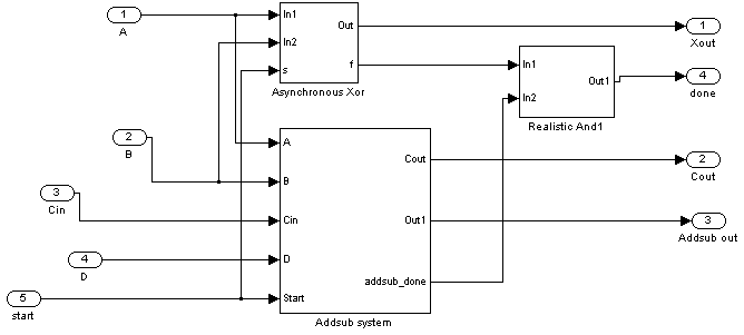
The next step is to create a one bit ALU. Each one bit ALU includes a 1-bit adder/subtractor, and a 1-bit Xor gate. Since the SLT is dependent on the adder/subtractor and outputs only zeros except for least significant bit, the SLT is not included in the ALU. The mux responsible for the final ALU output will select the adder/subtractor as the add and subtract output, the Xor gates as the Xor output, and 0 as the SLT output except for the least significant ALU block. The SLT functions by telling the adder/subtractor to follow A-B. If the output is negative, then output a 1 as the least significant bit of the 32-bit string. If the output is positive, then output a 0. The structure of the one bit ALU is shown below:
We tested the functions of the one bit ALU, one of which is shown below:
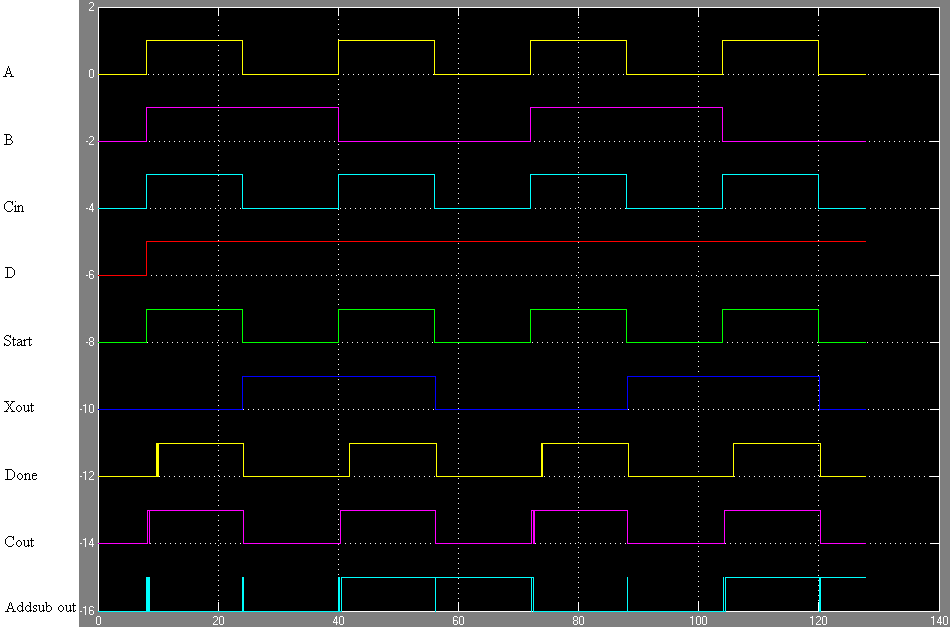
Take the 8-24 time block for example, input A and B are both 1. Since we are subtracting, Cin and D are both 1. As expected, when done is 1, the resulting XOR is 0 and the output is 0. The carryout only make sense for multi-bit addition and subtraction, therefore we are going to ignore the the carryout for the one bit on the test.
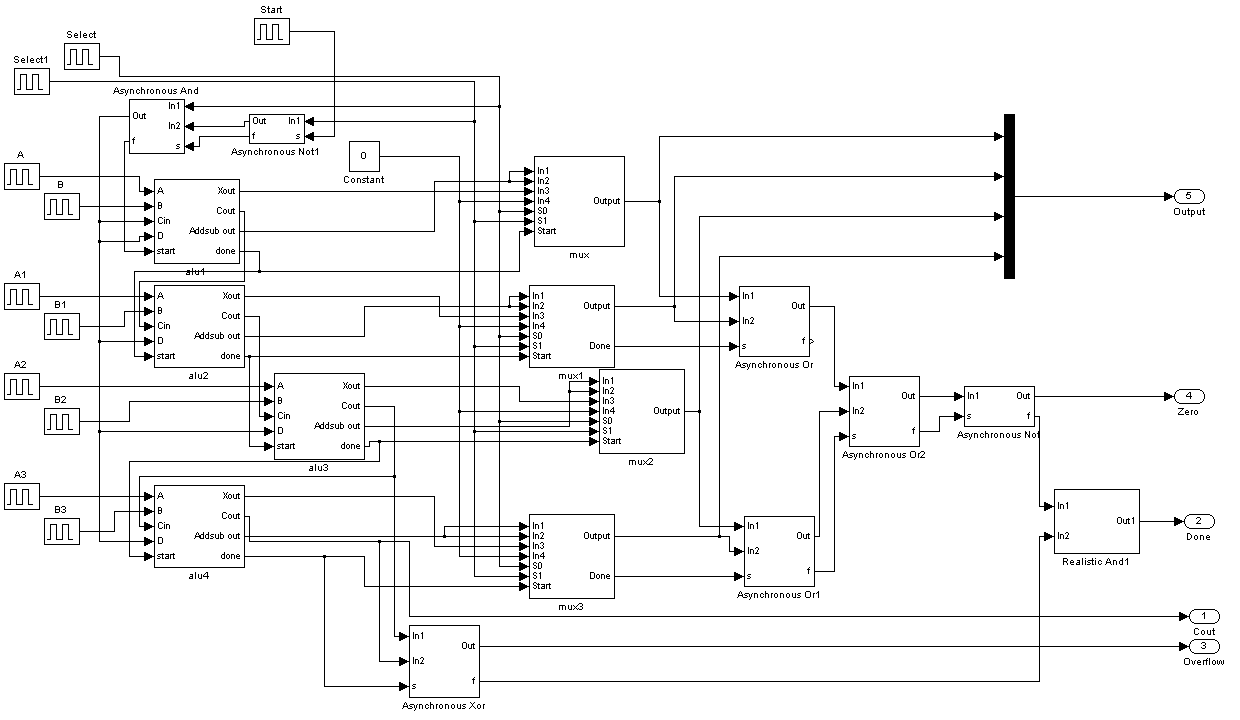
To make sure the structure is correct and to make testing easier, we made a 4 bit ALU first with all ALU features. Aside from linking four one-bit ALUs together, we have to modify our operation selector signal before putting it into the ALU adder/subtractor blocks and using multiplexors to string together the outputs. There are also a few more outputs: zero and overflow. The diagram of 4 bit ALU is shown below:
After testing the 4-bit ALU, we confirmed the functionality of the 1-bit ALU block. To build the 32-bit ALU, we assembled 32 of the 1-bit ALUs together in a scheme similar to the 4-bit ALU. The complete 32 bit ALU can be viewed and downloaded in our download page.